|
Mechanical Damage Risks for Sight Glasses - Pressure, Fracturing, and Impact Resistance

Click to watch a video talk on this segment
The most frequently discussed parameters with regard to sight window safety are mechanical. Indeed, these are significant factors that should be carefully examined. Mechanical damage can be categorized into three groups:
- Pressure driven blow out.
- Window edge crushing fracture from sealing stress.
- Projectile impact damage.
Pressure Driven Blow Out
This is the failure mode for which most claims of safety margins are made. All commercially available sight glasses exhibit gauge pressure safety factors of two to ten or sometimes even more. In other words, these units are designed to withstand gauge pressures ranging from twice the normal operating pressure to ten times or more. This is the "safety" that most vendors tout. Indeed, most vendors can truthfully claim that their products have never experienced a pressure driven blow out.
The reason for this seemingly reassuring record of "safety" is that preventing rupture is very easy; one can simply design the sight window with a thick piece of window material. Difficult part of pressure bearing sight windows is holding high pressures without leakage, not preventing ruptures. Calculation of how thick a pressure bearing circular sight window needs to be is a simple, undergraduate level calculation. In a nutshell, the pressure that can be held by a circular plate that is clamped along its circumference scales with the square of the ratio of thickness to the unsupported diameter, multiplied by a material/geometry scalar factor. This simple middle school level algebraic formula is all that's needed to correlate required pressure and window thickness, so anyone can design a sight window that can hold any level of pressure without concerns regarding pressure driven rupture.
This easy math is aided by a few convenient facts about materials, especially commercially produced glass. By its nature, large scale glass production is an exacting process that requires a large capital investment. Every commercial producer of glass controls the chemical composition of its glass very well, especially for high volume products like soda lime silicate glass, borosilicate glass, fused quarts, etc. So the material properties for the glass are completely unvarying, even for products from different vendors. Calculations can be performed with same material parameters regardless of the exact origin of the glass. Second is that glass can be produced in any desired thickness, and there are commercial operators that can fuse two pieces of glass into a much thicker single piece if so desired. In short, anyone can calculate how thick a piece of glass needs to be, and anyone can obtain the required thickness of glass.
One should note that there is little safety benefit to be gained by over-specifying the pressure safety factor. There is little chance of anyone' s calculating the required glass thickness incorrectly, so specifying a pressure safety factor that is greater than that of the rest of the process is pointless. There is no need to "round up" required specifications to address the possibility of incorrect calculation. Window edge crushing fracture from sealing stress
This is the most frequently encountered mechanical failure in conventional sight windows. The greatest stresses on sight glasses do not arise from the process pressure; usually, they arise from gasket seating stresses. Gaskets are plastic solids. As such, they need to undergo plastic deformation so as to fill out the tiny cracks on its mating surface so as to block flow of fluids through those cracks. The seating stress required to seal a sight glass tends to be orders of magnitude greater than the process pressure, especially for gases.
|
Style
|
T
|
M
|
Y (psi)
|
|
3500
|
1/16" 1/8"
|
5.0 5.0
|
2,750 3,500
|
|
3504
|
1/16" 1/8" 3/16" 1/4"
|
3.0 2.5 2.5 2.5
|
1,650 3,000 3,000 3,000
|
|
3510
|
1/16" 1/8"
|
2.0 2.0
|
2,350 2,500
|
|
3530
|
1/16" 1/8"
|
2.8 2.0
|
1,650 1,650
|
|
3535
|
1/4"
|
2.0
|
3,000
|
|
3540
|
1/16" 1/8" 3/16" 1/4"
|
3.0 3.0 2.0 2.0
|
1,700 2,200 2,200 2,500
|
|
3545
(in envelope)
|
1/16" 1/8" 3/16" 1/4"
1/8"
|
2.6 2.0 2.0 7.0 2.0
|
1,500 2,200 2,200 3,700 800
|
|
HP 3560
|
1/16" 1/8"
|
5.0 5.0
|
3,500 4,000
|
|
HP 3561
|
1/16" 1/8"
|
5.0 5.0
|
3,500 4,000
|
|
3565
|
1/16" 1/8" 3/16" 1/4"
|
2.8 3.7 5.5 6.0
|
1,400 2,300 2,800 2,800
|
|
3575
|
1/16" 1/8"
|
2.1 2.1
|
2,000 2,500
|
|
3591
|
1/16" 1/8"
|
4.3 2.0
|
1,650 1,650
|
|
3594
|
1/16" 1/8"
|
3.0 3.0
|
1,650 2,500
|
Table 1: Stresses needed for gasket seating. T=thickness, Y=minimum seating stress, M=maintenance factor, the multiplicative factor for preload to counter applied process pressure.
Table 1 lists seating stresses that are required to seal 2 PSIG of process pressure for Garlock Gylon gaskets, taken from the manufacturer' s product brochure. This is a commonly used product for sight window applications. T is the thickness in inches, and Y is the seating stress. M is the multiplicative factor to counter the process pressure; (m) x (design pressure, psi). Note that all of the values are over 1000 PSI, generally on the order of 3000 PSIG. For real, pressurized applications, the net operating stress needs to be scaled up with "M" factor shown in this table. In sight window applications, these values are not necessarily used; the minimum stress that seals the window is probably used more often. Glass is much weaker than other materials used in pressure vessel applications; if possible, it needs to be treated much more gently than other materials. But it should be obvious that stresses on the order of thousands of PSI are needed.
This 3000 PSIG minimum seating stress exposes the weaknesses of most transparent materials used for window applications. This seating stress is applied compressively on the gasket, and glass, like most structural materials, is able to withstand compressive stresses without limit. However, at the edge of the gasket seats, this stress morphs into a tensile component of roughly the same magnitude as the imposed stress. A simple finite element simulation shows this phenomenon clearly.
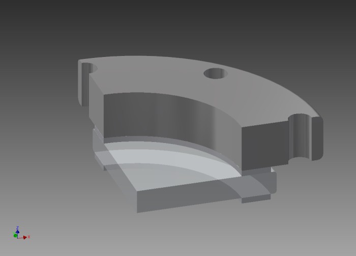
Figure 1: Model for finite element simulation.
Figure 1 is the model used for this finite element simulation, which is a quarter view of a circular glass held by 4 inch ANSI flange. Glass was modeled with soda lime silicate glass parameters, and the gaskets are modeled with Teflon parameters. The flange is shown for to make the picture easy to understand, but for the actual simulation, the compressive stresses were imposed directly on the gasket surfaces, and not transmitted through the flange. This simplification has the effect of "smoothing out" the stress profiles, so actual stress peaks in the glass will be higher than what is shown in this simple simulation, but the stress peaks shown in this simulation is still high enough to illustrate how the compression on the gasket still leads to a tensile component on the glass. The vertical boundaries of this simulation were treated with symmetry constraints that mimic a fully circular piece. The boundaries between glass and gaskets allow sliding, and the bottom surface of the lower gasket is fixed, simulating the gasket biting into the serrated face of an ANSI raised face. The upper gasket is loaded with 3000 PSI of downward pressure to simulate the minimum seating stress as recommended.
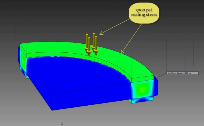
Figure 2: simulation results, for sealing 2 PSI process pressure.
Figure 2 shows the stresses within the glass for this loading condition. Note that the Von Mises stress in the glass at the edge of the gasket seat is about 2700 PSI. This is a reasonable result; inside that edge, the glass is seeing 3000 PSI stress under the gasket. Outside that edge, it is seeing zero PSI. So right at that edge, there is a very sudden change in imposed stress of 3000 PSI, and one should expect the glass to develop a deviatoric strain from this steep stress gradient. This is actually the most stressed point in the glass, not the center of the glass where pressure driven rupture would happen. And changing the glass geometry cannot alter this stress; the stress happens at the surface. And this region is where cracks are most likely to occur in real life.
For structural metals, 3000 PSI is well below their tensile stress limits, and can be tolerated indefinitely. However, glass exhibits very different strength characteristics than structural metals. On one hand, freshly manufactured silicate glass is as strong as structural metals. This strength of glass is the basis for fiberglass, whose structural strength is provided by its glass filament content. On the other hand, silicate glass is particularly sensitive to the presence of water molecules on its surface. Water molecules cleave silicon-oxygen bonds of silicate glasses, and initiate so-called Griffith flaws, which become crack initiators; once glass is exposed to moisture, it loses most of its tensile strength. This loss of strength can be avoided by coating the glass surface to keep water molecules away from the glass, which is how the strength of glass filaments is preserved in fiberglass. But without such protective measures, glass becomes an easily fractured material.
Since the strength of silicate glasses is greatly dependent on its aging history, particularly its exposure to water, strength tests of the kind used to characterize metals are inapplicable. In lieu of such, the glass industry has developed strength data for aged glass over long time periods, and uses that data as guidelines. Unfortunately, the acceptable working stresses for annealed silicate glass lie between 500 and 1500 PSI, and those for tempered glass lie between 1500 and 4000 PSI. These are maximum values with no safety margin, and depend on aging history. The 2700 PSI deviatoric component of the gasket sealing stress is already well above the lower figures of those ranges, and this was for sealing a 2 PSI process.
All of these factors result in the edges of the gasket seat area having to be subjected to higher stresses than what glass can tolerate in the long run. Indeed, the outer periphery of the glass, along the outer diameter of the gasket seat, is where cracks are most likely to happen. And unlike pressure driven rupture, cracks along the outer periphery of glass is observed often enough in service. This is the most important reason that sight glass vendors universally recommend regularly scheduled replacement of sight window glass. It is also why sealing high pressures is much more difficult than preventing catastrophic ruptures.
This issue is tolerable because this crack usually takes a long time to develop. So a regularly scheduled replacement of glass addresses it. Furthermore, the cracks along the outer edge of glass do not lead to immediate leaks, and do not represent obvious dangers, as long as the failing glass is replaced in a timely manner. One potentially serious issue involves sealing of leaks. If a leak develops in a sight window, the common response is to tighten the bolts that compress the gasket. This practice is tolerable to a point, but eventually the required stress for re-sealing a leaky gasket will be high enough to crush the glass beneath it.
The fact that this failure mode would result in slowly developing leaks does not mean there is no risk. If the process fluid is just water or steam, a slow leak would just be a maintenance hassle. But if it were a toxic liquid dripping into ground water, that still constitutes an unacceptable operational risk.
Aside from regularly inspecting and replacing the glass and gaskets, two other obvious solutions to this problem are available. First, one can use a fused glass sight window, in which the glass is melted into an outer metal ring. In this case, the gasket rests on the metal ring, so the seating stresses are never applied to the weaker glass. Second, one can use a sight window that is sealed along the outer wall, which de-couples the sealing stress from process pressure, and reduces peak Von Mises stress values. Projectile Impact Damage
Glass breaks. This fact has driven much research into different glasses and configurations that resist impact damage. However, for sight window applications, one should assess the magnitude of real impact damage risk present at any given location. All engineering projects are ultimately cost limited, and spending money on additional impact damage resistance means that there would be less money to spend on another part of the project. Does increased impact resistance reduce risk, or would failure risks be more effectively reduced by spending that money on some other feature of the process?
When assessing impact damage risk, one should recall that commercially available glass is actually pretty impact resistant already. Consider a common automotive wind shield, which is a large amount of relatively cheap glass. These windshields regularly absorb hits from little rocks that are thrown into air from automotive traffic, and these hits happen at 80 MPH. Most of the time, these glass surfaces simply deflect the projectile with little scarring, and cracking a windshield requires an uncommonly large rock being thrown into air. These impacts are much more energetic than any static structure is likely to endure from wind driven projectiles. For effective penetration, the projectile needs to be hard and dense, and the atmosphere is simply not dense enough to pick up such penetrating projectiles. Even hurricane force winds cannot pick up a rock larger than a small pebble. Note how rare a broken household window is; all those stained glass windows in European cathedrals have survived countless storms for hundreds of years. Even the weakest of pressure bearing sight windows is much stronger than these household windows.
If there is real impact damage risk, there are many available options for enhancing the impact resistance of glass. Strategy falls into two categories - shielding and compressing. The most common method for providing shielding is probably lamination; two pieces of glass are glued together. Each piece of glass is thick enough to hold the rated pressure with an appropriate margin of safety. In case of a fracturing impact, the fractured piece, usually the outer piece, serves as the shield for the surviving piece, which contains the process fluid. Along the same principles, other transparent shields can be used to protect windows. For example, a thick, transparent polycarbonate glass-typical "bullet-proof" glass-can be used to shield the sight glass.
All glass strengthening involves inducing compressive stresses on the surface of the glass. The most common method is thermal tempering, in which heat treatment is used to impose compressive stress on the outer skin of a glass piece, which is balanced by tensile stress at the core of the glass. Also common are chemically strengthened glasses; ionic species of different radii are diffused/exchanged into the outer skin of glass, inducing compression. Finally, the whole volume of that glass can be held in compression by fusing it into a metal ring, which produces makes the glass very impact resistant.
Thus, if a real impact risk exists, there are a number of possible solutions at different costs. One application in which there is significant impact damage risk should be noted-a large, horizontal sight window installation. Sometimes, man-ways or hatches incorporate sight windows. If these are horizontal openings, then it is possible for a worker to drop a hard item, like a bolt or a nut, onto it, and inadvertently step on it. This scenario will probably result in a catastrophic failure of the glass, and needs to be thought through.
< Back to Introduction
| This web site is provided by: |  | Copyright 2015, All Rights Reserved. |
|
 |
|
|