Model I Weld Sight Glass
Assembly Instructions
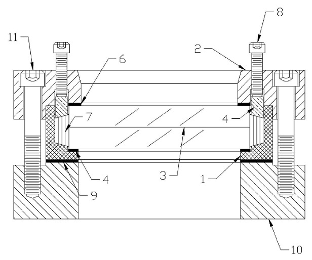
This unit was assembled for shipment and the bolts were purposely not tightened. Before unit is welded to the vessel, the unit must be disassembled by removing the bolts. retainer cap, lens, packing, cushion gaskets, insert cup, and mounting gasket. Weld only the weldment block (10) to the vessel. Use an appropriate welding procedure to minimize distortion of the weldment block. After the weldment has cooled the unit may be completely reassembled by following the steps below.
When installing parts, refer to steps (A) thru (P).
- (A) Place the insert cup (1) on a flat surface, serrated face down.
- (B) The interior of the insert cup (1) must be clean.
- (C) Place the bottom cushion gasket (5) (largest ID) into position.
- (D) Carefully place the lens (3) on the bottom cushion gasket (5).
- (E) insert the packing (7) between the lens (3) and the interior wall of the insert cup (1) in a normal packing procedure.
- (F) Place the one piece compression ring (4) on the packing (7) bevelled side down.
- (G) Place the top cushion gasket (6) (smallest ID), on the lens (3) and inside the I.D. of the compression ring (4).
- (H) Take the retainer cap (2) and slip it on the insert cup (1). The compression ring (4) must fit into groove in the retainer cap (2).
- (I) Once the retainer cap (2) is in position, install the 1/4-20 cap screws (NOT SHOWN) into the counter bore in the retainer. Due to the non-compression of the packing (7), the retainer cap may ride on the compression ring (4). If this occurs tighten the 1/4-20 cap screws until the insert cup (1) and the retainer cap (2) make contact.
- (J) lnsert the compression adjustment screws (B) and tighten across diameters. At this point do not completely tighten the screws.
- (K) The sight glass sub-assembly is ready for installation to the weldment block (10).
- (L) The weldment block has cooled and is clean and free of any weld splatter.
- (M) Place the mounting gasket (9) on the weldment block and set the sight glass sub-assembly into position on the gasket.
- (N) Once the sub-assembly is in position, install the socket head cap screws (11) and tighten to provide a seal with the mounting gasket (9).
- (O) Repeat step (J) by tightening the compression adjustment screws (8).
- (P) Occasionally, when pressure is applied, the packing (7) will loosen. Should leakage occur, follow the tightening procedure outlined in step (J), until leakage has stopped.
| |